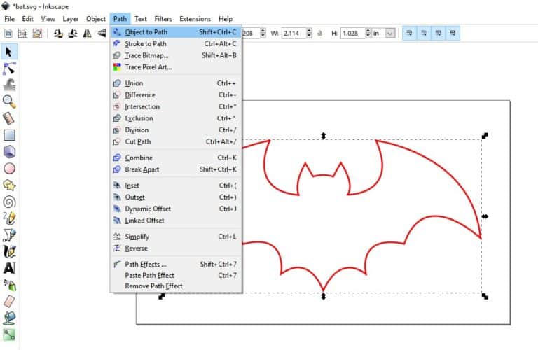

As well as this, every 'object' on the board is surrounded by a rectangle - that is, if the drawing shows a hexagon (for example), the Gcode for the hexagon is in the. Its not every block, and there appears to be no 'pattern' to which block is duplicated that I can see. However, this file appears to have some 'oddities': almost every Gcode 'block' is duplicated - if I run the file on the router, it carefully mills the shape I drew, then goes round it again. This all appears to work fine, and I end up with a Gcode (.ngc) file. I then import this SVG file into Inkscape, and go through the usual procedure to generate a Gcode file - Object to Path, Tools Library, Orientation Points and Path to Gcode (all from the Gcode Extension). (when displayed with an image viewer - Pix in Linux) As far as I can determine, the resulting exported SVG files appear to only consist of these lines.
Inkscape gcode series#
Basically the layout is simply a number of copper 'lands' on the board, so the drawing is just a series of lines between the lands which will be milled out. I need to produce some printed circuit boards by etching them with the router (long story), and started by producing a drawing of what I wanted in LibreOffice Draw, and exporting it as an SVG file.
Inkscape gcode how to#
Here we discuss How to create G-code in Inkscape along with the two methods by which the users can create the code.I'm using the Gcode extension in Inkscape to generate Gcode files for a small CNC router, and after making loads of mistakes learning my way around (and being helped by this forum - Inkscape is brilliant for what I need) I have another issue. On the whole, Inkscape is an accomplished program having multiple functions and tools for every purpose.
Inkscape gcode download#

Set the orientation source and nature of the extrusion that needs to be created. For this, go to Extensions> g-code tools> Orientation Points. Next, we need to enter the orientation source and points of the shape to be cut within the 3D printer.The user can modify the settings from the boxes. Similarly, different boxes will be created with the other layers as well.The user can click on the box and edit the settings from there if needed. A green box will appear for the 1 st layer that specifies preferences for the G-code.This method has to be done for every individual layer one by one. Select CONE from the dialog box and click Apply. These are options given to the user to select the tool for the way of cut they want. Now, go to Extensions > G-code Tools and select Tools library.The shapes should be adjusted in such a conduct that they appear as a 3D shape with hard edges.Again add a layer and copy the same shape on this layer.

Create a new layer by going to Layer> Add a layer.Still, without utilizing any external program, Inkscape is capable to create G-code for machine purposes.įollowing are the steps to create G-code in Inkscape:. This technique is proficient but, it may sometimes be a confusing or time-consuming process for the users.

So, to use G-code for 3D printers we need to create a 3D effect to get the desired results. Since we all know that Inkscape is not a 3d program. While in the 2 nd method the users will require an additional program to convert and view the G-code and the output. With the 1 st method, users can create G-Code for Inkscape files with the Plugins and Extensions already available in the program.


 0 kommentar(er)
